Equipment Required
- Oscilloscope, 10 Mhz triggered sweep or better.
- Digital Voltmeter, Beckman 310 or equal.
- A known good Omnichrome laser.
- Line power of at least 20 amp service 108-125 VAC 50-60 Hz.
Make up a standard remote plug for testing. Jumper pins 36 to 37. This jumper is part of the interlock circuit. The laser willnot work wihtout this jumper. Connect a SPST switch between pins 34 & 35. This will serve as teh stand-by switch.
For current control operation, connect a 100k pot between pins 1 and 25, wiper to pin 6. For light control operation with the pot on the laser head, jumper pins 3 & 4. For light control with the pot on the power supply, jumper pins 3 & 2.
1. Connect laser head to power supply, connect remote connector to power supply.
2. Remove top cover; (12) #6-32 x 1/4 screws. Place supply so you will face the open side. Plug in power supply. Turn on rocker switch only at this time. Note: The 532 head fan will come on.
3. Using the digital voltmeter verify the +/- 15VDC, +/- .35v across C19 and C20, located to the left of IC3 near the front edge of the PC board.
4. Next, check the voltage at IC2 pin 7. During cathode delay and stand-by it should be +13 to + 15 VDC.
5. Check the voltage at IC2 pin 1. During cathode delay and stand-by it should be +13 to + 15 VDC.
6. Using a scope check the waveforem at TP2. It should be a square wave from +12VDC to -12VDC, +/- 1VDC, with a duty cycle of about 70% positive. (See fig 8)
NOTE: Operating frequency will be in the 100 to 110 Khz range. The actual frequency is not critical, as long as it is within limits. The duty cycle is very important as it will affect the starting of the laser.
7. If the duty cycle is not correct, please check the following: 1. During cathode delay (no laser current) check the voltage at R40 pin 1. It should be between +0.3 to 1.0 VDC. If not, adjust R35 for the correct voltage. Check at the cathode of D15 located next to R39 pin 14. It should be aprox. -1.0 VDC. Adjust R37 stand-by pot for correct voltage. Finally, adjust R33 duty cycle pot for correct waveform.
8. Verify the gate drive signal by putting the groudn ref of the scope to Q8 & 9. Source the probe tip to the gate of the FET's. NOTE: The scope must be isolated from ground. The waveform should be similar to Fig 9. Set the scope for 5 V/div and 2 microseconds/div. Trigger is positive. NOTE: Signal is GND to +15VDC.
9. If everything checks out, turn on the key switch enabling the filaments and starting the 34 second cathode delay. Check teh filament voltage at the connector to the laser head, pins 1 & 22. At nominal line voltage the filament voltage should be 2.7 VAC +/- 0.1VAC. If not, set the voltageusing switch SW1. Position 1 is the lowest setting, position 8 the highest. NOTE: Turn off the key switch when setting the voltage. Failure to do this could damage the switch contacts!! After the cathode delay the laser should light. After the laser is on, let it warm up for 5 minutes. Then set stand-by current (using R37) for a 4.5 to 5 amp reading at teh tube current jacks located at the head. (Use 2 volt scale on the meter) Read as 0.2 volts per amp.
10. Normal waveforms are as follows:
Figs 10 & 11 - IC1 pin 13 at 4.5 and 11 amps laser current.
Fig 12 - TP5 at 4.5 amps.
Figs 14 & 15 - gate waveforms at 4.5 and 11 amps.
Fig 16 - Drain waveform at 11 amps.
Fig 17 - Drain and gate turn off at 11 amps laser current.
Fig 18 - Drain and gate turn on at 11 amps.
Fig 19 - line current with laser running at 11 amps.
Fig 20 - inductor L1 current for 11 amps laser current.
Fig 21 - a TEM00 laser set for low noise correctly adjusted.
Fig 22 - the same laser using an isolation transformer.
Fig 23 - optical noise with noise pot turned all the way down.
Figs 24 & 25 - Loop gain pot misadjustment.
Got Problems??? Check Here
NOTE: A laser head that is known to be good must be used with these tests. If in doubt, check head with a known good power supply.
Symptom Number
1. No fans, no LED on head, no lamp on supply.
Causes: Check power supply main fuses. Check AC main circuit breaker. Check line filter continuity.
2. No lamp on supply, but LED on head is on.
Causes: Fuse F3 is open. Interlock circuit open (check cables and plugs). SW1 open, filament transformer bad. J3 loose. R22 open. RLY2 bad. D4 shorted. Bad key switch.
3. No head fan. LED on head is on. Filament lamp is on.
Causes: Fuse F4. 5 amp pigtail fuse open. Head fan plug loose. Fan bad. J2 loose.
4. Tube won't light. No flashes. Everything else OK.
Causes: Fuse F5 open. J8 loose. R35 offset pot misadjusted. R33 duty cycle pot misadjusted.
5. Tube lights then winks out.
Cuases: Loop gain pot R34 misadjusted. Stand by current set too high, or too low. Offset pot R35 misadjusted. Noise pot set too high. C35 open.
6. Tube lights, but power supply squeals audibly. Sometimes winks out.
Causes: Loop gain pot R34 misadjusted. Noise pot set too high. C35 open. Note: On some models the loop gain is fixed by resistors, a 27k pin 1 to ground and a 43k pin 9 to pin 1. Remove the resistors and install a loop gain pot (50k). The holes are already provided.
7. Tube just winkes.
Causes: Duty cycle pot R33 set incorrectly. FETS Q8, Q9 shorted. Offest pot R35 misadjusted. Stand by pot set too low.
Model 150R Circuit Description
The Omnichrome Model 150R Argon Laser power supplies are state of the art high frequency switching power supplies. It is designed to provide long life with minimum service or adjustement. The supply provides several functions including remote control and remote monitoring. A 35 second timer is provided as part of the interlock so the laser cathode can warm up to a safe operating temperature. After the cathode delay, a relay is activated providing high voltage starting boost. Laser curent level is accessible on the laser head red and black banana jacks. Here the current is read as .2 volts DC per amp of laser current. CAUTION: THE RED AND BLACK JACKS ARE AT LINE POTENTIAL. Therefore use an isolated meter. Laser output power level is accessible at the head between the blue and yellow jacks. The calibration may range from .2 volts/mW to .005 volts/mW. These are the only signals that can be obtained on the laser head. These nd many other signals are accessible in the power supply and at the remote connector.
Start Up and Stand By
Laser start up is initiated by turning the key switch and enabling the interlock and delay timer. Before starting the laser of a new or repaired power supply, check and set duty cycle according to set up instructions in this manual. Setting the duty cycle limits the starting current to a safe value. When power is applied to the circuit a voltage applied to IC2 pin 5 forces the output high thus turning off the FET Q4, a J176 P-channel FET, and enabling the duty cycle pot R33 to take effect. When the laser lights, the output of IC2 pin 7 goes low (-13VDC). This turns on the FET and removes R33 from the circuit and establishes control of the duty cycle by current demand. This signal (the output of IC2 pin 7) controls the light and current preamps by turning off the N-channel FETS Q5 & Q6 tus enabling these preamps. When the standby switch is turned on (shorting remote connector pins 34 & 35) it forces the integrator output high and asserts control of output current by turning on Q5 & Q6 removing the feedback signal from the control loop. Then the stand by pot output is the only signal feed to the summing amp, except for feedback from the current feedback (hall-effect) circuit.
Low Voltage Power Supply
The low voltage power supply consists of T1, F2, D1, D2, C1, to C6, and IC5 & 6. The primary has windings for 110VAC and 220VAC. For 110V operation connect pins 1 to 2 and 5 to 6. For 220V operation connect pin 5 to pin 2. Please refer to the schematic diagram. The supply consists of a half wave rectifier and a voltage regulator for the +15VDC and the -15VDC outputs. An AC signal is also provided through R26 to the timer circuit.
Adjustments
Loop Gain R34
NOTE: To set the loop gain pot, turn the control clockwise while watching the optical output signal. When the supply oscillates, back the control 1/8th turn counter-clockwise. CAUTION: Turning too far in either direction could create problems (see figs 20 & 21).
Another method is to adjust the loop gain pot back and forth until a point is found that seems to be stable. Then turn up the noise pot until the unit just starts to oscillate, then turn the loop gain back and forth until a spot is found that doesn't oscillate. Repeat this procedure until there is only one place the loop gain pot can be set to prevent oscillation. NOTE: The noise pot can be set so the supply will always oscillate. Do not turn it up too high. At this point refer to the next section to set the noise.
Optical Noise R36
Unless your application requires verylow optical noise, the noise pot is set for a noise reading of 3.5% to 4% p-p. NOTE: The lower the noise setting, the greater the chance that the supply will osciallte. The actual noise depends upon the optical power. The percent noise goes down at high power levels.
To read percent noise on a scope using a power meter only, follow this procedure. Set the laser power at the level you wish to measure noise. Using DC coupling, set the deflection on the scope for 5 major divisions. Then switch to AC coupling and turn the vertical gain up 10x. The noise is read as 2 percent per major division.
The procedure for setting the noise pot is to turn the pot all the way counter-clockwise, set the scope as above, and view the optical power output from a power or noise power meter (see fig 8). Turn the pot 2 to 3 turns clockwise while watching the noise on the scope. The noise should drop rapidly then level off. At this point when the adjustment rate slows down, the pot should be backed off 1/2 turn (see fig 19). This is to prevent oscillation as teh plasma ages. If difficulties are encountered it may be necessary to adjust the loop gain pot in conjunction with the noise pot. BE CAREFUL. Misadjustment could result in oscillation and damage the supply if left unattended.
Cathode Warm Up Delay
The 35 second timer consists of the circuitry IC4 (a CD4040BE), a 12 bit binary counter, relays RLY1 & 2, and a thermal switch (TS) located on the heat sink, and associated components. A 60 hz AC signal is provided to pin 10, the clock input of IC4. An enable signal at pin 11 is the reset input when teh key switch is activate, pulling pin 11 to ground via R27. The counter then counts the 60 hz signal until a logic "1" is sen at pin 1, the Q12 output. The high "1" at pin 1 turns on Q10 and pulls in relay RLY1. At the same time, the signal is returned to pin 10 via a signal diode (D22). This puts a logic "1" on pin 10 and stops the counter. If at any time the interlock circuit opens, a logic "1" at pin 11 resets the counter and turns off RLY1. Therefore, the cathode delay works off of the interlock circuit to proved a guaranteed 35 second delay. The thermal switch has been added in the Model 150R in case of fan failure or excessively hot conditions.
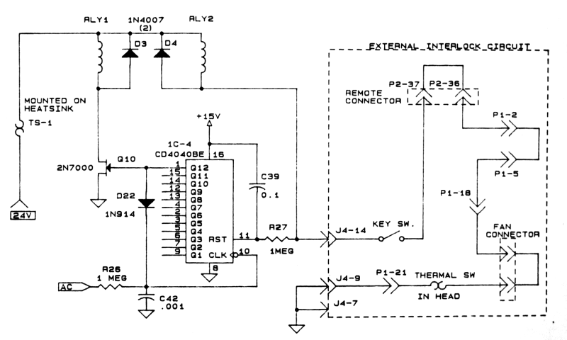 |
| Fig. 1 |
High Voltage Start Boost
The start voltage boost is the signal used to ignite the laser tube. The start boost circuitry is a voltage multiplier consisting of diodes D58, capacitors C30-C33, and resistors R28, R31, R101, and R112. On the Model 150, the start boost is a voltage quadrupler. A failure in this circuit results in no start voltage or pulse in the head circuitry.
There are two ways to test the boost circuit.
First, in the power supply, connect a voltmeter to Q9 source. Set the meter to the 1500 volt scale. Connect the positive lead to R28 (the end closest to SW1), a 100k 5 watt resistor located on the right side of the supply next to J8. You should measure approximately 150 VDC during warm up. After warm up, the voltage climbs rapidly to about 550 to 650 VDC until the pulse circuit in the head triggers, then the voltage should drop to about 150 VDC. The other end of R28 will then measure the total boost of around 600 VDC +/- 50 VDC.
Another way to check the boost circuit is to measure tube voltage before the start pulse. Hook the meter negative to the tube filaments, either wire, and the positive to the cathode (top) of the 1N1190RA blocking diode. CAUTION: DO NOT CONNECT THE VOLTMETER TO THE PLASMA TUBE ANODE. THE START PULSE COULD DAMAGE YOUR METER. The voltage during warm up shoudl be about 150 VDC. When the time times out and RLY1 pulls in, the voltage should climb to about 550 to 650 VDC, then the start pulse triggers and the tube should light. When this happens, the voltage drops to about 100 to 110 VDC depending on tube current.
If the tube doesn't light, the voltage would drop to the initial charge after the trigger pulse occurs, then charge back up until the trigger pulse occurs again. This cycle will repeat about once a second until the tube lights or the supply is turned off.
 |
| Fig. 2 |
FET Drive
The FET drive circuit consists of Q1, 2 & 3 and FETS Q8 & 9, transformer T2, capacitors C8, 9, 10 and 34, resistors R1 thru 5, R9 & R11, and diodes D19 and zener D11. The drive signal comes from IC1 pin 13 (see figs 11 & 12) as a square wave of approximately 10 volts p-p. The signal is amplified by Q1, 2, & 3 and is approximately 25 volts p-p at test point TP2 (see figs 8 & 9). It is transformer coupled and appears as a 15 volt p-p signal at TP5 (see fig 13). NOTE: WHEN MEASURING THE SIGNAL AT TP5, BE SURE TO ISOLATE THE OSCILLOSCOPE FROM CHASSIS GROUND. USE Q9 SOURCE FOR COMMON. This signal is fed to the FETS via R11, 8 & 9. D19 allows the gate of the FETS to discharge faster. The signal appearing on the gates of the FETs will be rounded by the capacitance of the gate (see figs 10 & 14). When everything is right, the signal at the drain of the FETs will have a rise time of approximately 100 ns (see figs 16, 17 & 18). The duty cycle is determined by the current required to operate the laser.
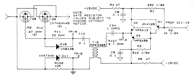 |
| Fig. 3 |
Control Electronics
First, the "inner loop" consists of IC1, IC2, FET drive, and current feedback. IC1 is a regulating pulse width modulator. IC2, a TL074ACN, is a low-noise J-FET input quad operational amplifier. The laser current signal is fed back via R16 into the inverting input of IC2a, pin 2, the summing amplifier. This amplifier with its carefully controlled feedback drives the PWM chip to control current in the laser. The minimum laser current or standby current signal is summed into the amp from the R37 standby pot via R39d. This is a negative voltage approximately -0.6 to -1.2 VDC measured at the wiper of R37. Clockwise pot movement raises laser current. This is the voltage required at the summing junction to offset the feedback signal (and keep the summing junction at a virtual ground) in order to keep the laser plasma tube current flowing at a keep alive level of approximately 4 to 5 amps DC. Duty cucle is set suring warm up. Use R33 and adjust for a duty cycle of approximately 70% on. IC2b is an integrator and is used to force the PWM chip to a fixed duty cycle by turning off Q4 and allowing R33 to take affect. During warm up or stand by, the voltage on the output of IC2b is approximately +13 VDC. When the current feedback signal appears on R15 the integrator goes negative (approximately -13VDC) forcing Q4 to turn on thus shorting out R33 and allowing the PWM chip IC1 to respond to the current control signal at pin 2. Check the loop-gain pot R34 for proper adjustment as described in the adjustments section.
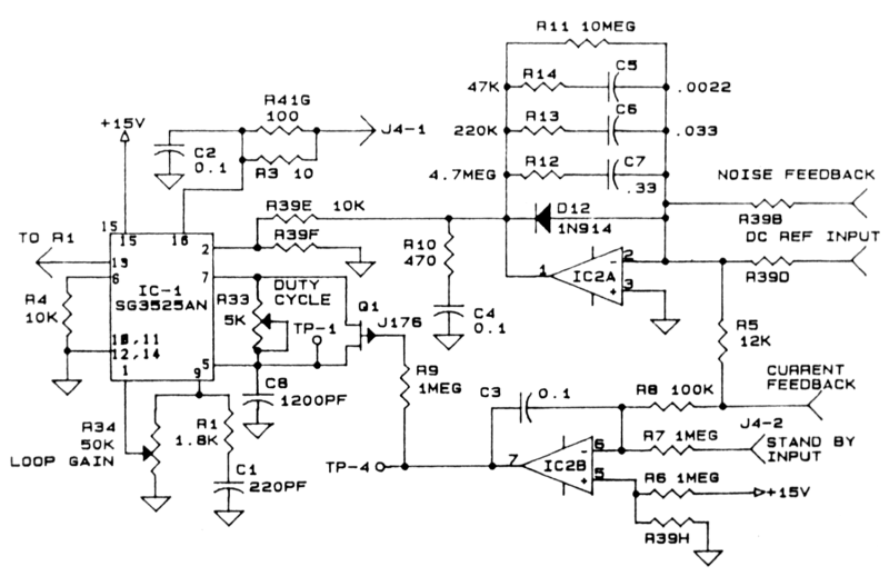 |
| Fig. 4 |
Light Control
This circuit is know as the "outer loop". The light control feedback signal appears at R42b,c pins 12 & 13. This signal is buffered via R42c into IC3a pin 3 (non inverting) input.It appears at the remote connector pin 29. It also is buffered through IC3b and is applied to IC3d via R42d. The AC signal from IC3d is fed through diode D13 and a 1.0 mfd capacitro to the noise pot R36. The DC signal is routed through RR110 to the current limit pot R38. The DC feedback establishes the current at which the laser will operate. Using light control, the output is regulated by the DC level of the signal from the optical sensor mounted in the head. This is a function of the optical power emitted from the laser. The actual signal levels are determined by the calibration setting in the head preamp. The AC or noise signal is summed in the summing amp and used to cancel some of the nouse that is present in the optical signal.
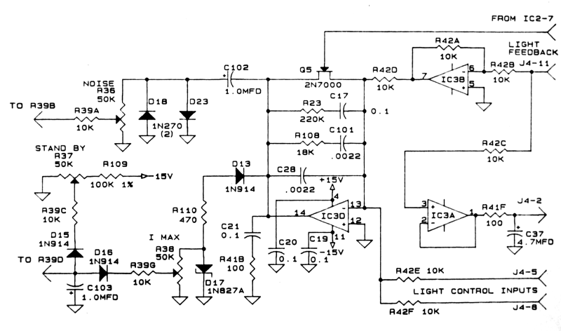 |
| Fig. 5 |
Current Control
The current control signal is fed back from the current out signal at the remote connector pin 36. It is connected to the current control preamp IC3c via pin 10. This signal is routed through IC3c and D14 into R110 and current limit pot R38. Control is accomplished by applying a positive DC voltage to the remote connector pin 6 of about 1 volt per amp of desired output current. This voltage is summed into IC3c via R25, As the input voltage goes positive the output goes negative. This is coupled to the summing amp via R39d. As the current increases, the DC level of IC3c goes more negative thus driving the summing amp output more positive and increasing the duty cycle.
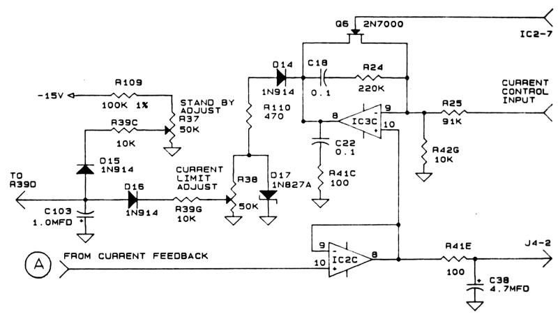 |
| Fig. 6 |
Current Feedback Circuit
The current feedback circuitry consists of IC2d, R40a,b,c,d, & e, R12, R13, R35, R41a & d, C29, C16, Q7, and L2 (a 1000 turn toroid with a hall effect sensor located in a gap in the core). Offset pot R35 is used to adjust the voltage at R40 pin 1 to about +0.6 VDC. This zeros the current in the coil. The anode lead is fed through the toroid, setting up a magnetic field in the core. The opamp supplies enough current into the coil to null out any magnetic field induced by the anode lead. This appears as a voltage across R41a (a 100 ohm resistor in series with the coil) as 0.1 V per amp of anode current. This voltage is fed back to the control look opamp (IC2a) via R16. It also is buffered and shows up as the laser current output signal at the remote jack via IC2c pin 8. This signal is used to determine if the laser is working and control a comparator (IC2b) that switches the unit out of standby and into run mode.
 |
| Fig. 7 |
Remote Connector Pin Out
Pin Function
1,23,27,30 - Circuit ground. Use for all measurements outside chassis.
2 - Light control potentiometer on supply panel.
3 - Light control reference input.
4 - Light control potentiometer on laser head.
5 - External light control imput. 0 to +nV will increase.
6 - External current control input. Approximately +1.0 V/amp.
8 - Chassis ground.
9 - +5.1 VDC reference test point,
24 - -15 VDC output. (50ma max, for external preamp, etc)
25 - +15 VDC output. (50ma max, for external preamp, etc)
26 - Tube current test point +0.1 V/amp of tube current.
29 - Milliwatts test point +nV/mw (per calibration of head).
34,34 - Connecting together will put laser into stand by.
36,37 - Interlock. Must be connected together for operation.
NOTES:
Light level control of laser head (Current-pot, minimum)
Normally, pin 3 is connected to pin 4, allowing light control witht eh level pot in the laser head. If you wish light control using the potentiometer on the power supply front panel, connect pin 3 to pin 2.
Current control of laser head (Light-pot, minimum)
For remote current control of the laser head, connect a 10k potentiometer, CCW end to pin 1 on remote connector, CW end to pin 25, and the wiper to the pot on pin 6.
If you wish current control using the potentiometer on the power supply front panel, make the same connections as above on the back side of the remote connector, but inside teh power supply.
Before making this change, remove the existing potentiometer wires and insulate them, remembering that this weill eliminate light control at the power supply panel. All circuits in the remote connector are referenced to circuit ground and thru a 1 meg resistor to chassis ground. If the remote connector is connected to other circuitry, it is best to use small inductors in every wire followed by a 0.1 mfd capacitor from each wire to either circuit ground or chassis ground, whichever is more effective in reducing the noise level on the wires. If extending wires on pins 3 and 6, you should use shielded wire, with the shield connected to chassis ground at the supply end only to avoid conducting noise back into the supply control circuitry. The inductors may be about 100 uh @ 70mA or larger.
Additional Figures
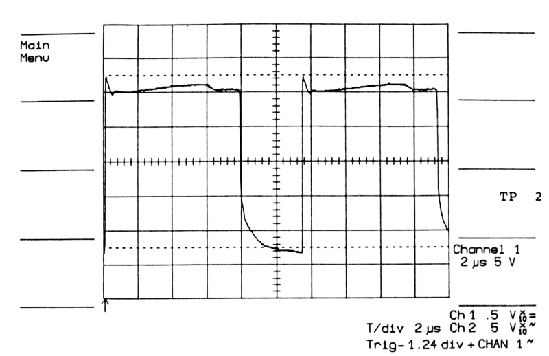 |
| Fig. 8 - Picture taken during cathode warm up |
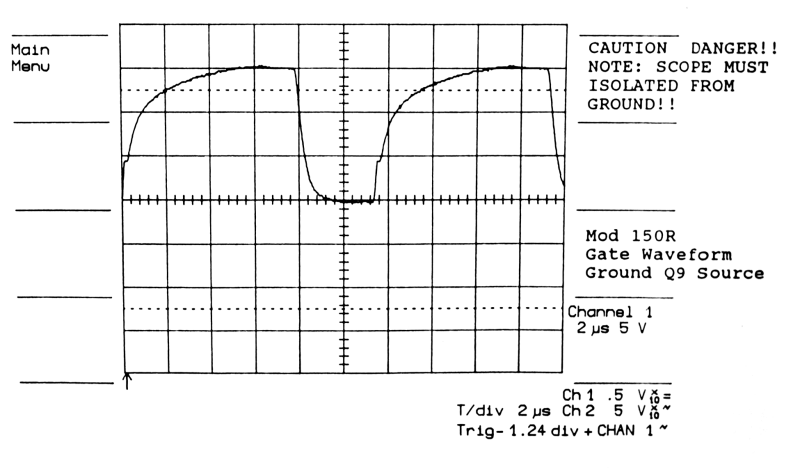 |
| Fig. 9 - Picture taken during warm up |
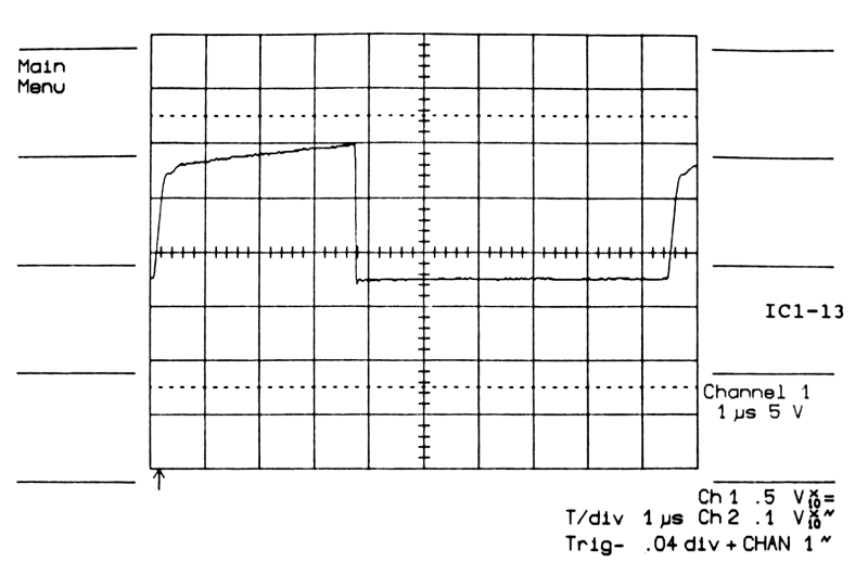 |
| Fig. 10 - Laser running at 4.5 amps |
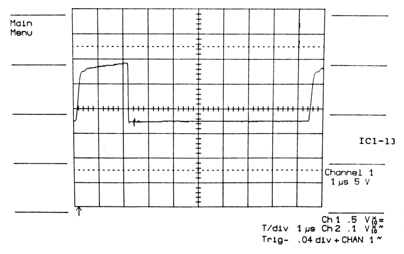 |
| Fig. 11 - Laser running at 11 amps |
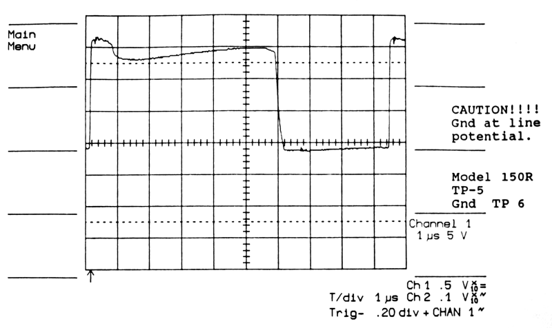 |
| Fig. 12 - Laser running at 4.5 amps |
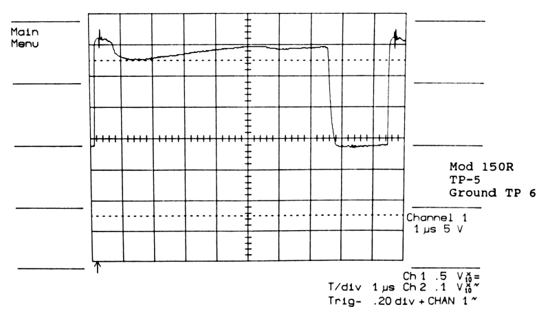 |
| Fig. 13 - Laser running at 11 amps |
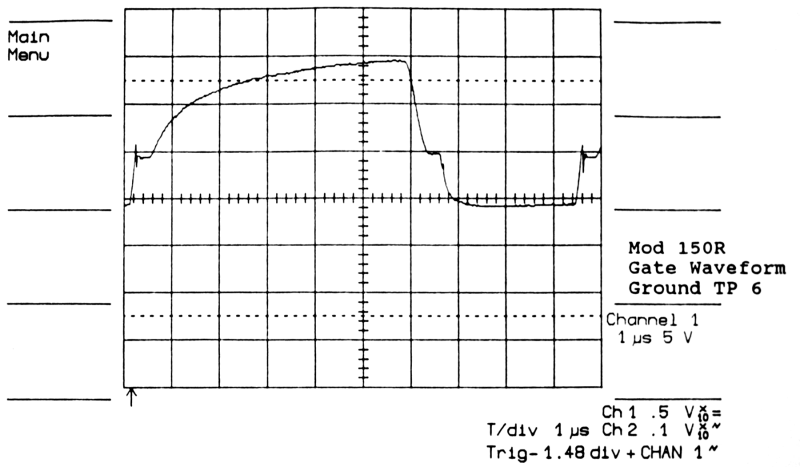 |
| Fig. 14 - Laser running at 4.5 amps |
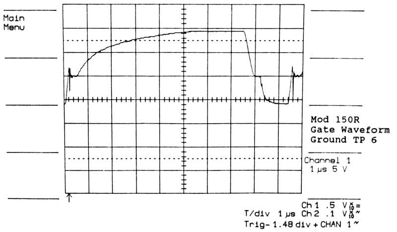 |
| Fig. 15 - Laser running at 11 amps |
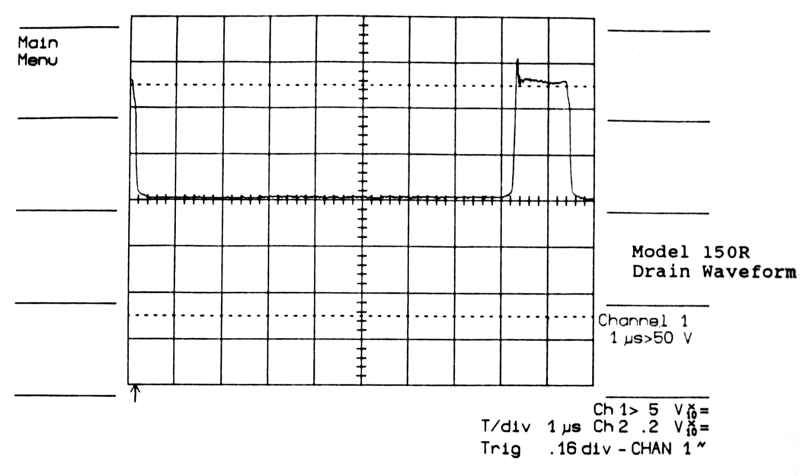 |
| Fig. 16 - Laser running at 11 amps |
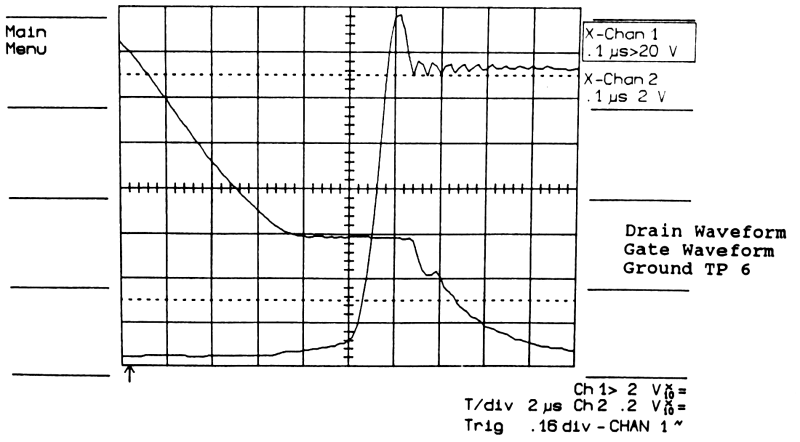 |
| Fig. 17 - Laser running at 11 amps |
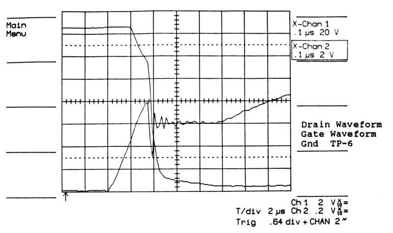 |
| Fig. 18 - Laser running at 11 amps |
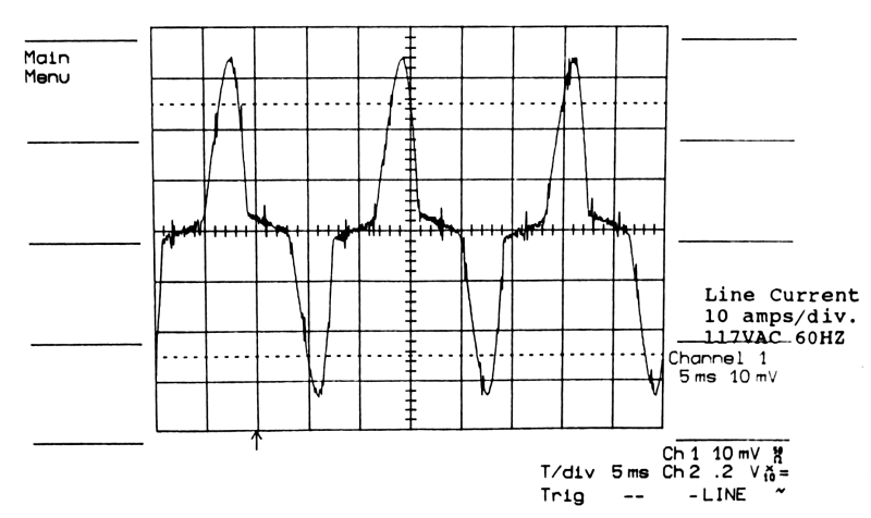 |
| Fig. 19 - Laser running at 11 amps |
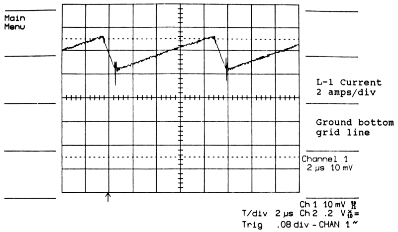 |
| Fig. 20 - Laser running at 11 amps |
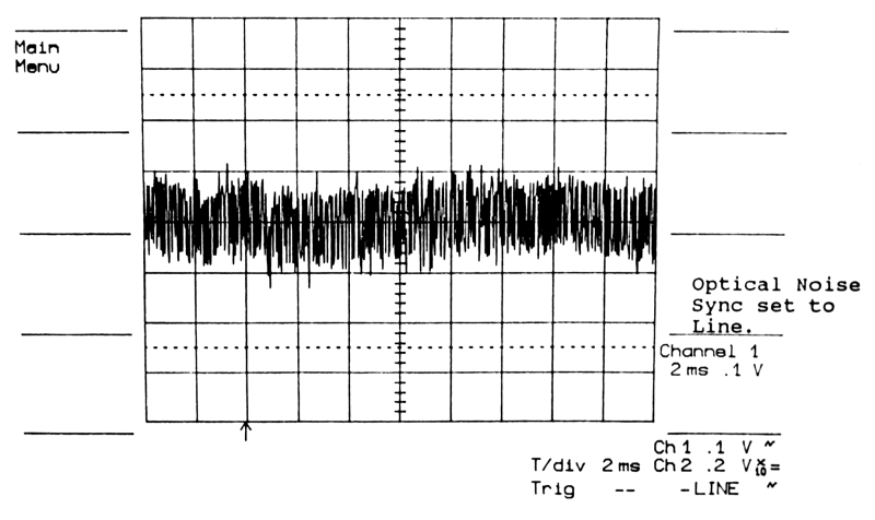 |
| Fig. 21 - A TEM00 laser set for low optical noise NOTE: For this waveform a power or noise power meter is necessary. Connect the scope to the power jacks at teh rear of the meter. |
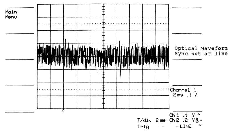 |
| Fig. 22 - The same as Fig. 21 but with an isolation transformer NOTE: For this waveform a power or noise power meter is necessary. Connect the scope to the power jacks at teh rear of the meter. |
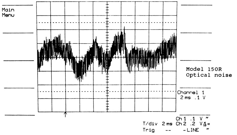 |
| Fig. 23 - Optical noise pot R36 turned all the way down NOTE: For this waveform a power or noise power meter is necessary. Connect the scope to the power jacks at teh rear of the meter. |
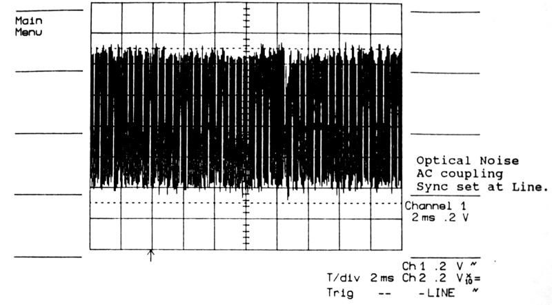 |
| Fig. 24 - Loop gain pot R34 misadjusted counter clockwise NOTE: For this waveform a power or noise power meter is necessary. Connect the scope to the power jacks at teh rear of the meter. |
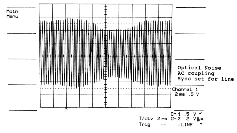 |
| Fig. 25 - Loop gain pot R34 misadjusted clockwise NOTE: For this waveform a power or noise power meter is necessary. Connect the scope to the power jacks at teh rear of the meter. |
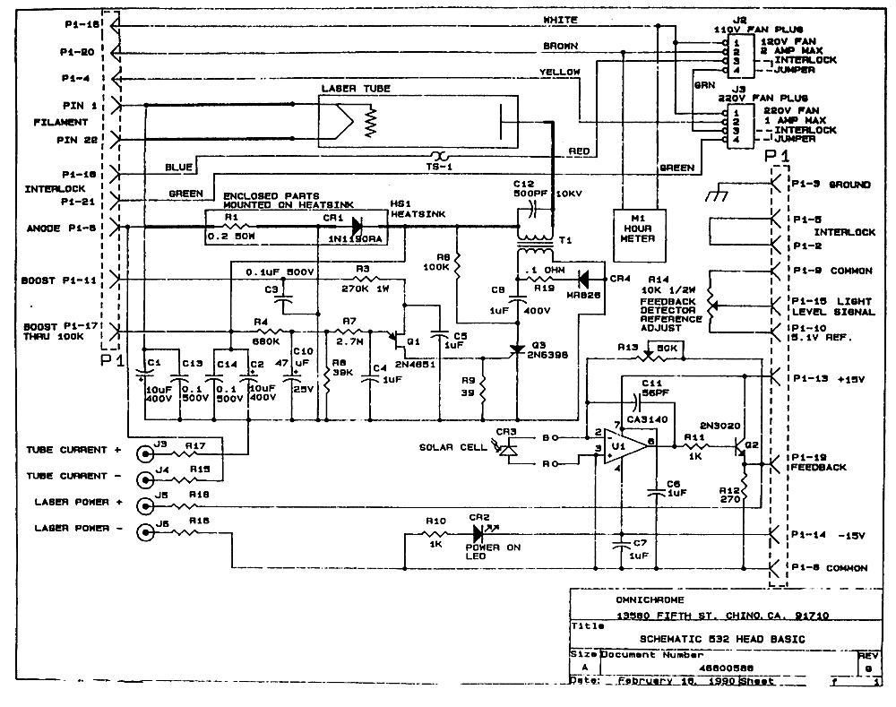 |
| Schematic |